Edge Autonomy Summer Internship Projects Summary
July 2023
Edge Autonomy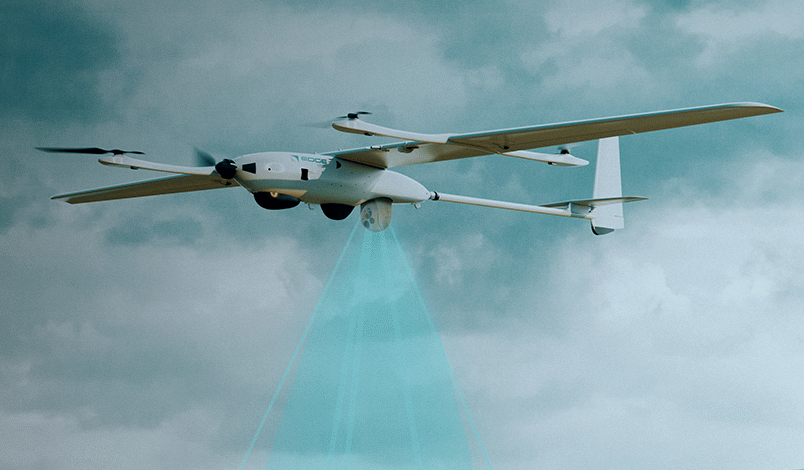
In the winter quarter of freshman year, I took IME-145 - Subtractive Manufacturing Processes for Mechanical Design, taught by Kyle DeBernardi. The room was full of mechanical engineers, including alumnus DeBernardi, so he shared what his professional life has been like since graduating from Cal Poly. He described some of his newer job at Edge Autonomy in town, an autonomous surveillance drone manufacturer. He’s the Director of Production, and upon my questioning he got more specific about his responsibilities; in general working to improve and streamline the production process and achieving higher production rates.
Nine weeks later and I was walking out of the door of the IME lab for the last time when I asked DeBernardi if they do summer internships. He excitedly requested that I email my resume. I did so the next day, then had an interview the following week. The interview with my current boss, Trevor Gronner, went great and everything was set for me to start the second week of summer.
I first started out with the pre-preg composites technicians. For two weeks, they taught me how to make a few of their carbon fiber and fiberglass parts, including the vacuum bagging process. By the last few days, I was able to make several parts on my own.
On the third week, my boss Trevor asked if I knew how to use SolidWorks. I told him I had used Fusion 360 quite a bit but had little time in SolidWorks, though the two should translate. He agreed, then passed one of his projects off to me. It was very simple, just adding some handles from McMaster to a new mold being designed. It required adding counterbored holes and importing the handle STEP files from McMaster. I surprised Trevor by picking out several types of handles and making several configurations so he could see different combinations of handles; folding handles, straight handles, bent handles, etc.
When he saw I was competent using CAD, he brought be back to the pre-preg team to help them create a custom tool they’d been requesting for a while. Read more about that project below (Fuselage Rotisserie Stand).
After that first project, I’ve been almost exclusively designing jigs to improve accuracy and precision across the production floor. Below are some of the more involved projects I was assigned.
Projects
Fuselage Rotisserie Stand
Ergonomic fixture to make carbon fiber layups of complex fuselage mold more efficient, and less physically taxing for technicians
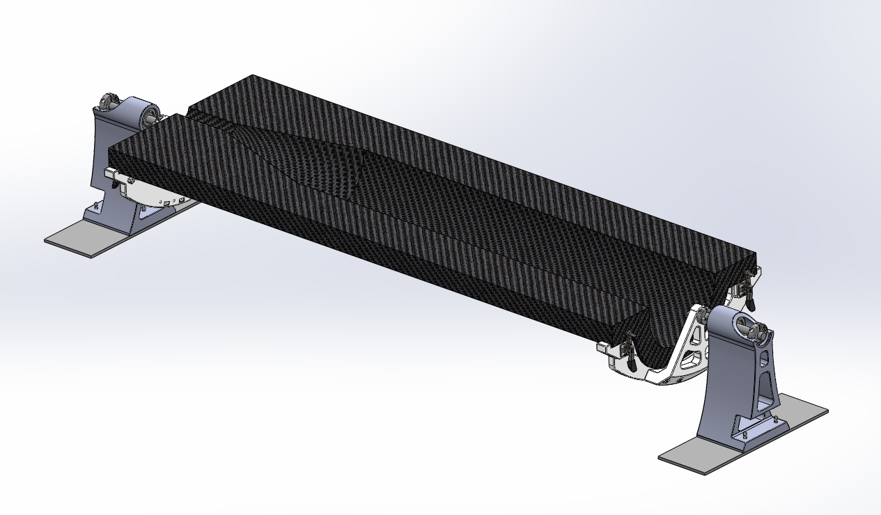
The Fuselage Mold Rotisserie Stand was my first project at Edge Autonomy. After spending about a week in the pre-preg composites department, my creative thinking and SolidWorks abilities were put to the test to design this jig.
The fuselage mold in the pre-preg department is a large and awkward piece of equipment to work with on its own. After the first two weeks of my internship, I had seen my coworkers spend hours on their feet working around the table with the mold for almost the entire day. One of them suggested that if they could rotate the mold then they wouldn’t have to be hunched over or walk around the table.
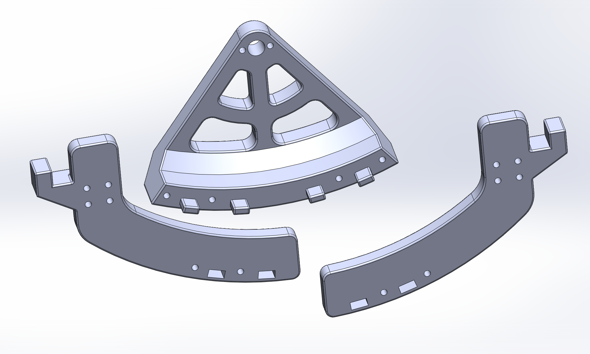
I sourced parts from McMaster-Carr and modeled everything in SolidWorks thanks to their useful CAD files for all their components. As I was preparing to have the main parts 3D printed, I realized I didn't know the build volume of the printers in house. It turned out that my original model was too large for the print bed, so a redesign was necessary. The new design featured 3 different parts assembled with nuts and bolts. For alignment and strength, I added locating "pins."
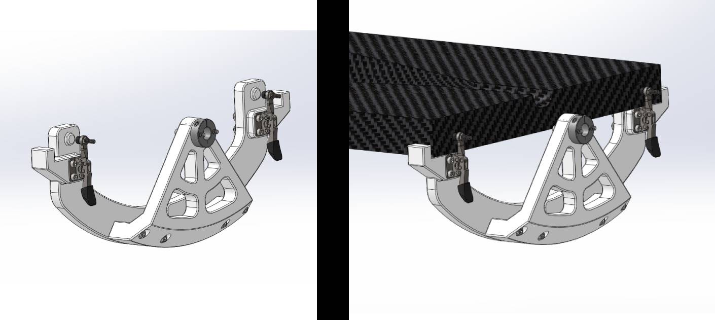
On the first test, I borrowed the rotisserie jig from the finishing department, and put the fuselage on. Working with the Composite Techs, we criticized the design and worked together on what features it should have moving forward. We determined that the existing rotisserie stand hardware was too tall, and could be shortened to make thing less awkward at a standing position.
Something I had not considered until this test was that they work with two mirrored sides of the fuselage mold. My design had a “nose” end and “tail” end, but that forced one half of the mold to be upside down compared to what the techs were used to. A very simple fix was apparent: mirror the nose-end clamp. The nose side was much more complex than the tail side to accommodate the greater mold depth. It worked perfectly for the tail-end, in the end making the jig easier to use with both sides of the mold, as well as making it more symmetric and presentable.
When the techs and I were brainstorming together, we came to the conclusion that the lower the mold can get to the table, the better. It was great having the entire tool modeled in SolidWorks, because I was able to shorten the stands to achieve an extremely small clearance, bringing the mold essentially as low as possible on the table.
As I write this, the Composites Technicians are familiarizing themselves with their new tool. I see them using it when I'm on the floor, and I'm happy to see that they look much more comfortable, sometimes even sitting down. In general, making this tool was a great project. I got to collaborate with my new team, and my creative-engineering mind was challenged in order to improve the process of producing fuselages in house.
Threaded Hole Jigs for Wings
Drill jigs to ensure critical tap points are perpendicular to the curved wing surface
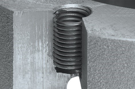
On each wing of the drone, there are several holes that need to be threaded and given a Helicoil Insert, and so far that process has been done entirely by hand. The human error in precision was much higher than the allotted tolerance, resulting in many wings being outright discarded, not just a waste of material but especially a waste of labor. I was asked to make several jigs that technicians could use to get the right tap and Helicoil angle every time.
This was my first exposure to working with complex surfaces in CAD. Using the existing wing models, I started with a jig that was a complete outline of the wing profile. It would ensure the correct angle and vertical spacing of the tap using drill bushings as guides, and had unique locating features corresponding to different holes across the length of the wing.
However, the complete outline of the wing proved to be too tight of a fit. The technician had also received a perpendicular tap guide that was easy to use on the wing profile because the holes are on parts of the airfoil that are close to flat.
More parts of the wing needed tapped holes and Helicoil inserts. I made more tap jigs which proved to be very helpful.
There were several more locations for Helicoil inserts around the wing that I also designed jigs for.
After a few days of the tap jigs being used, one of the lead techs approached me asking for similar tools to guide the Helicoil insert tools at the correct angle. One of the requests was to be able to see the insert as it entered the wing – like a little window. That meant I wouldn’t be able to use drill bushings. I opted to make jigs that would hold the Helicoil tool straight, not the actual Helicoil. A large chamfer that intersects with the tool holes made the insert visible as requested.
Examples:
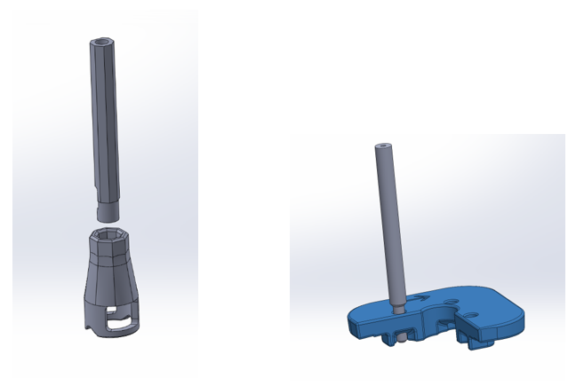
I also made a handle accessory for the helicoil tools, making operation more similar to a tap with a T-handle, more optimal to ensure angular accuracy than the default crank-style handle.
Carbon Fiber Mold Locating Tools
3D printed jigs to easily ensure minimum clearances and ply locations
Throughout the summer I made many tools to assist the pre-preg composites team. For every layup, they were making repeat measurements from holes and other features to ensure specific clearances. Trusting that they remembered the right measurement and that they were using the rulers at 90 degrees was far from an optimal situation.
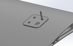
To improve accuracy over repetition, I made jigs that are quick and easy to place on the mold and immediately locate up to 3 reference points.
The time spent making the same measurements was significantly improved, as well as trainability of the complex layup, and due to the nature of the mold, there is no choice but for the minimum clearances to be met, improving the number of parts that make it through QC.
Example ply locating tools:
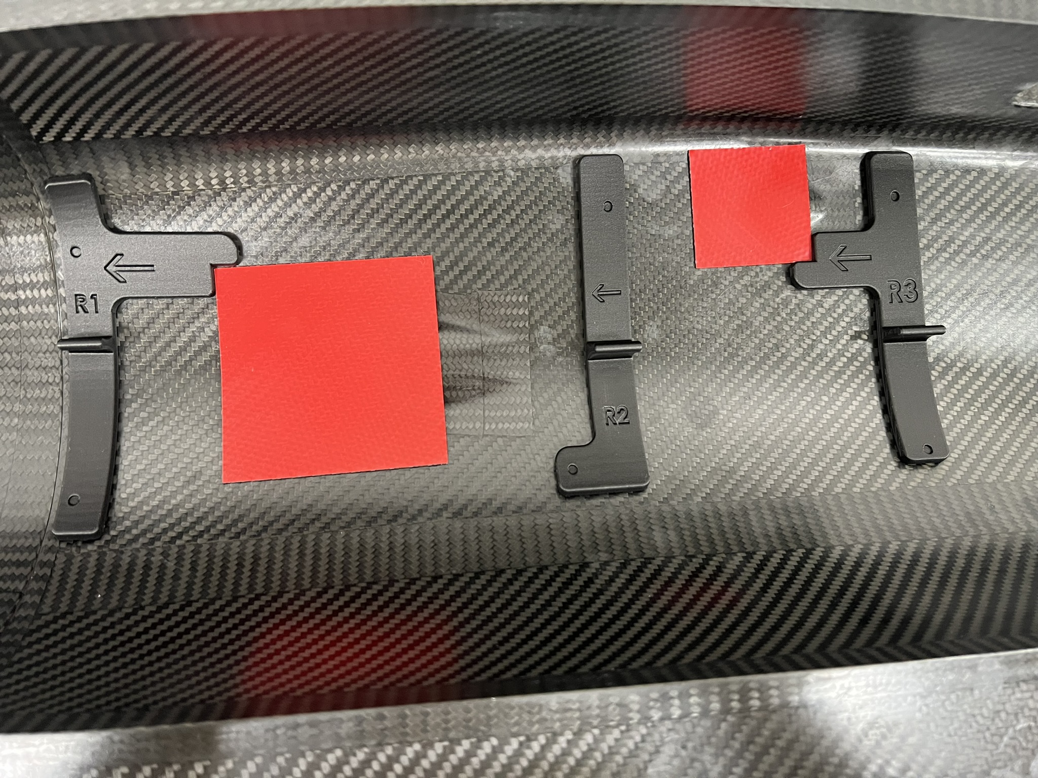
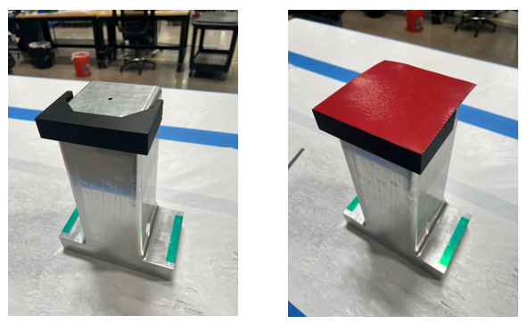
In the Battery Box mold as seen in figures 2 and 3, the top ply placement was very crucial. Many more plies are later placed alongside its edges, which must be almost perfectly parallel to the bottom edge. Before, this alignment was being achieved by measuring the width that the ply hangs over the edge in 2 locations on every side; at least 8 measurements. Careful trial and error slowly got the ply closer to centered and straight. Now, techs only need to snap my tool around the edges of the mold, then align the ply with the corners of the tool. Stick the center down and remove the tool, then it’s all good to go!