Bicycle Crank Power Meter for ME-507 (Spring 2026)
June 2026
GitHub Repo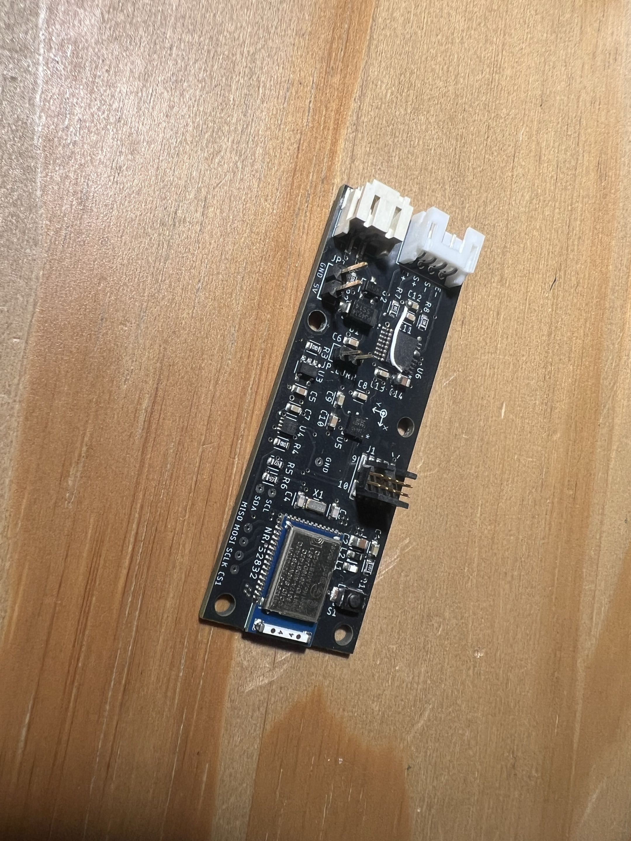
Bike Power Meter
Intro
This project was for the Mechanical Control System Design course (ME-507) at Cal Poly, often referred to as "Mechatronics III". The course involves a project of a student's or team's choice that meets a minimum criteria, and design a custom PCB to assist in performing that task.
For my project, I chose to make a project I'd thought about for a long time - a power meter for my bicycle cranks that interfaces with my bike computer (Wahoo Elemnt Bolt v1). It works on the principal of Torque * Angular Velocity = Power, but generating those values reliably is no easy feat.
One of the requirements of an ME-507 project is that it incorporates closed loop control or similarly complex control algorithms. Since my project does not have any physical outputs, there is no feedback to be collected for closed-loop control. As such, my "similarly complex control algorithm" was to implement a Kalman filter to fuse the IMU data from the gyroscope and accelerometer to get much more accurate angular velocity data. Originally, I'd hoped to also generate a map of average power output at different locations in a crank stroke. This ultimate fell out of scope due to a lack of strain gauges on both cranks, and a lack of strain gauge DOF to measure in which direction the rider is pushing on the pedal, as commercial power meter pedals can measure.
Design
The design process began with determining what type of data I would need to collect, and what protocol(s) I would need to be able to output. After much research, I settled on a 6-axis IMU (ICM-40609), a full bridge strain gauge with high-resolution ADC (ADS1220), and a MCU capable of operating BLE service. Originally, I'd planned to use the now-deprecated protocol "ANT+", so I chose the nRF52832 chip, but overtime it proved to be much more valuable to use the BLE Cycling Power Service standard - one reason being that it is much easier to debug with my phone or laptop without special ANT hardware.
Once I had my necessary components selected - ICM-40609, ADS1220, and nRF52832, I had to design the PCB to house it all. As my instructor warned, it was a very iterative process. Beyond supporting the minimum necessary components for proper functionality, I was also trying to balance several other considerations. First was size: it should be small enough that I can secure it (inside a housing) to my bike crank without interference with my shoe or the bike frame, though at the same time the board and component selection shouldn't be so small that I couldn't re-work traces if needed. I settled on a board size just under 1" x 2".
Manufacturing
Once I had my PCB design completed (to my best ability at the time), I sent my manufacturing files to JLCPCB for assembly. I was very intimidated by RF design on the PCB, so I opted to use a SoC package of the nRF52832, however JLCPCB did not support the component at the time of ordering, so I had to mark it as do-not-place and do it myself once the PCBs arrived.
Once the incomplete boards and nRF52832 SoC's arrived, I used a hotplate to finish assembly.
Initial Testing
The initial power-up was extremely nerve-wracking, to say the least. A lot was riding on these boards working, especially my wallet. First the voltage supply was isolated and powered up. Once the voltage was verified, I had no choice (due to my design) but to power up the rest of the board. Thankfully, all systems were responding - the ADC, the IMU, the SoC, and also a battery monitor (MAX17048) I included for future battery status reporting in future versions of the firmware.
Firmware
With the selection of a Nordic MCU came learning a new workflow. At first, I used Segger Embedded Studio, because it was the only way to write code for the deprecated ANT+ profiles, but once I found out I could use BLE services, I switched over to the modern nRF Connect SDK in VS Code. It was a very steep learning curve for me. I'd never heard of "device trees" before, or used CMake to any significant extent. Additionally, I only had minimal exposure to pure C embedded development, so that also took a lot of referencing docs and examples to develop an understanding.
I began with mini projects to verify I could read from each subsystem - battery monitor, IMU, ADC, and BLE communication. Once those were working, I combined them into one large project. It was immediately apparent that I would need to spend a good amount of organizing the repo in preparation for it to grow. I settled on a system where each thread I wrote (for each subsystem) had its own file. The file tree grew quickly, but each file is significantly easier to digest.
The next major hurdle to overcome was implementing the Kalman filter to fuse the accelerometer and gyro data. I'd found existing projects very similar to this for applications like drones, however my system experiences constant rotation, such that the centripetal acceleration is significant enough that it must be included in the predictive model. The centripetal acceleration element also made the system non-linear. After some research, I found this repository containing the framework for an extended (non-linear) Kalman filter for embedded applications - thank goodness.
Now, I could focus on just the model and Kalman matrices, no longer worrying about how to implement the complex matrix math in C. I settled on a 5 state system:
- Angular position
- Angular velocity
- Gyro Bias
- Accel X Bias
- Accel Y Bias
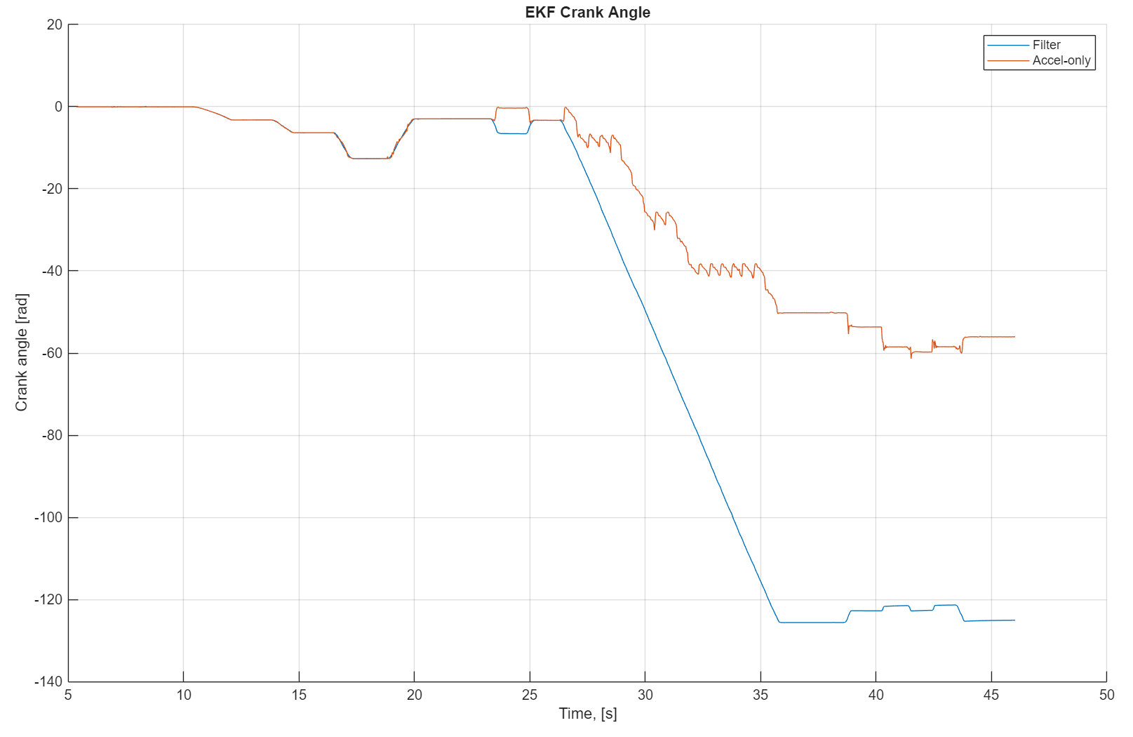
After much trial and error and workshops with my controls professors, I finally got it working. Comparing filtered vs. raw data in MATLAB proved that the filter was working very effectively, ignoring much noise independent to the accelerometer or gyro, and tracking a steady angular position. Using just the accelerometer with a high RPM and low sample rate, it can be impossible to tell if the device rotated very little in one direction (i.e. 10deg) or very far in the other direction (i.e. 350deg), but with the additional information from the gyroscope, the angular velocity helps inform the filter of the actual velocity/displacement. The figure below from MATLAB shows how angular data is lost from a high RPM and low sample rate when using raw accelerometer data, but maintained when using the filter.
Hardware testing
Since I made this in college, budget and space are both at a minimum. I don't have spare bike cranks lying around to test on, nor do I have enough space to work on the project with an entire bicycle at my desk. Instead I made a desktop rotational load system, consisting of an aluminum rod connected to a steel shaft that has significant rotational damping. With this bench testing rig, I could adhere strain gauges to the aluminum rod and measure torque as I applied force to rotate the rod around the shaft. This was the rig I used to verify the Kalman model.
Bluetooth communication was also a steep learning curve for this project. But by the time I was at hardware testing, I was on track to start trying to transmit data to the bike computer. Luckily, there is a standard protocol, so I didn't have to reverse anything on a proprietary bike computer. Unfortunately, the standard protocol was not the clearest thing to understand, and took a long time to get right in my implementation.
Finally, with a desktop testing rig, all systems communicating, and working Kalman filter, and a BLE connection to my bike computer, I had a working proof of concept!
Next steps
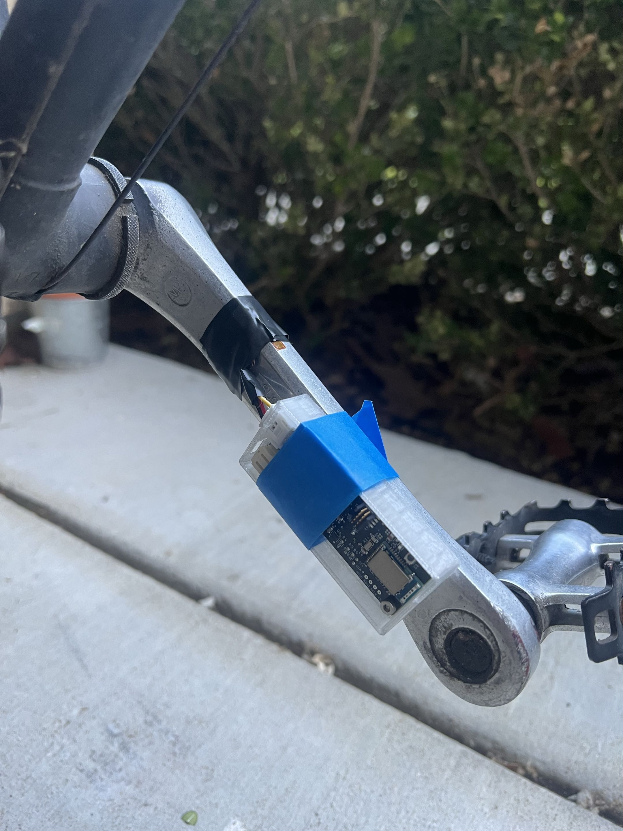
Eventually, I would like to move this project to an actual bike of mine. The only concern is the strain gauges. The surface prep and adhesives are pretty intense, and would ruin the paint finish on my powder-coated aluminum cranks. I have a few other bikes but they have carbon cranks and I'm not even going to attempt to mess with those.
For now, I can continue to comb through the firmware, then eventually add power-saving features like auto-sleep and auto-wake with IMU data. If there's ever a time that I can afford to purchase another round of PCBs, there are several changes I would make to the board:
- Of course, fix up mistakes that required physical rework - I forgot to connect EXC+ and EXC- on the full strain gauge bridge to VDD and VCC.
- Connect additional features from system peripherals, like DRDY on ADS1220, INT1 and INT2 on ICM-40609, and ALRT on MAX17048.
- Use an isolated nRF52832 MCU, no more SoC. I'll use an external antenna to put my RF concerns at rest.
- Switch to smaller components and make the board size smaller. Explore small debugging header options
- Add built in Li-Po charging IC(s) and corresponding input connector (USB-C?)
- Add status LEDs (only very short flashes to save battery)